Visual Instruments
Voltage Monitor
Voltage Monitor
Couldn't load pickup availability
Voltage monitor from Visual Instruments helps pilots monitor critical electrical system.
With all the advances and improvements in electronic navigation technology, many pilots are upgrading their aircraft with new GPS, moving maps displays, and EFIS equipment, making them more dependent on reliable electrical power. Loading up the “boat” (aircraft) with too many of these new electronic devices can easily out-pace the electrical generation capacity and greatly reduce battery reserve after a generator or alternator failure.
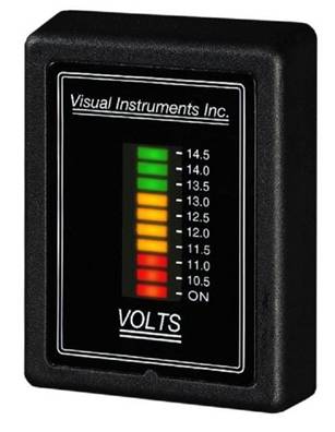
Visual Instruments has received STC approval for it its new digital voltmeter monitor. The instrument features a Multi-Color LED display, which is easily viewable from a wide angle. A configuration switch on the back of the unit sets the display to either Bar Graph (shown) or Dot Mode. The range of the display is expanded making even small voltage fluctuations very noticeable. This is particularly important in IFR operations where small changes in ammeter needle movements often go unnoticed. On most aircraft instrument panels, the ammeters are usually located way to the right, outside the normal instrument scan pattern, making them extra difficult to see. Parallax makes them hard to interpret from the left seat. Most pilots don’t even realize they have alternator failure until after their radios quit working. Then it’s too late to shut down unnecessary equipment and conserve precious battery energy.
In the event of an alternator/generator failure, the Visual Instruments Monitor LED display indicates the reserve battery capacity in a fuel gauge fashion providing a better indication of how much time is left before battery exhaustion. The display automatically adjusts to the ambient light for IFR or night operation and also serves as a reminder to turn off the electrical system after flight.
The Voltage monitor comes in either 12V or 24V models and includes all necessary hardware and FAA Documents. It typically takes a mechanic less than one hour to install and fill out the necessary paper work. The display must be set to Dot mode for FAA approved installations.
In the short time the monitor has been available, it has been credited with over four saves, two of them in actual IMC (when pilots lost their electrical charging via alternator or generator failure). This voltage monitor thus alerted the pilots immediately to those failures so they could shut down any unneeded systems to preserve battery power and not have a complete loss of electrical power prior to landing. Over 300 aircraft types are on the FAA approved list. To see if your aircraft qualifies for this STC or for more information, contact Visual Instruments.
Share

Documents
Supplemental Type Certificate (STC)
Approved Model List (AML)
Installation Instructions
Frequently Asked Questions (FAQs)
Why do I need a Voltmeter when my aircraft already has an Ammeter?
In detecting and diagnosing electrical system problems, voltmeters have many advantages over the factory-installed ammeters. They also indicate how much battery reserve is left after an alternator/generator failure.
I noticed that Visual Instruments sells several different Voltage Monitors what is the difference between these different models?
Besides being FAA approved and built to PMA standards, P/N 2000-26000 /12-volt model and P/N 2000-2650 / 24-volt models include automatic dimming.
How long will it take my mechanic to install the Voltage Monitor?
A good mechanic should be able to perform the installation in about an hour.
This includes making the logbook entries and filling out all the FAA paper work.
When we developed this product we went to great lengths to make the installation simple, and provide the necessary forms pre-filled to make the process as quick and painless as possible.

